WAVE OPTICS
- Aniket Verma
- Dec 4, 2023
- 5 min read
Updated: Dec 11, 2023
JEE MAIN CHAPTER OVERVIEW
Chapter Priority | 3 (LOW) |
Number of problems in PYQ | HIGH |
Difficulty | MODERATE/HIGH |
To solve JEE MAIN problems for Wave Optics, you need to remember all formulae given in these notes.
Note: Questions in the exam are easy if you know the concepts well. Focus on understanding interference which forms the basis for Young's Double Slit Experiment.
KEY CONCEPTS FOR JEE MAIN
WAVEFRONT & HUYGEN'S PRINICIPLE
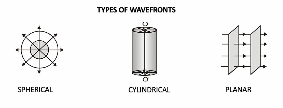
Light is an electromagnetic wave which emits disturbances in all directions. At equal distances from the source in a single medium, all particles are vibrating in phase. The locus of all such points that are in phase is called a wavefront.
Spherical Wavefront
A point source will produce a spherical wavefront in a single medium since all equidistant points are in phase.
Cylindrical Wavefront
A linear light source will produce a cylindrical wavefront.
Plane Wavefront
At very large distances from the source, a a small portion of a spherical or cylindrical wavefront will appear to be planar.
Huygen's Principle
Each point of the wavefront is the source of a secondary disturbance and the wavelets emanating from these points spread out in all directions with the speed of the wave. These wavelets emanating from the wavefront are usually referred to as secondary wavelets and if we draw a common tangent to all these spheres, we obtain the new position of the wavefront at a later time.
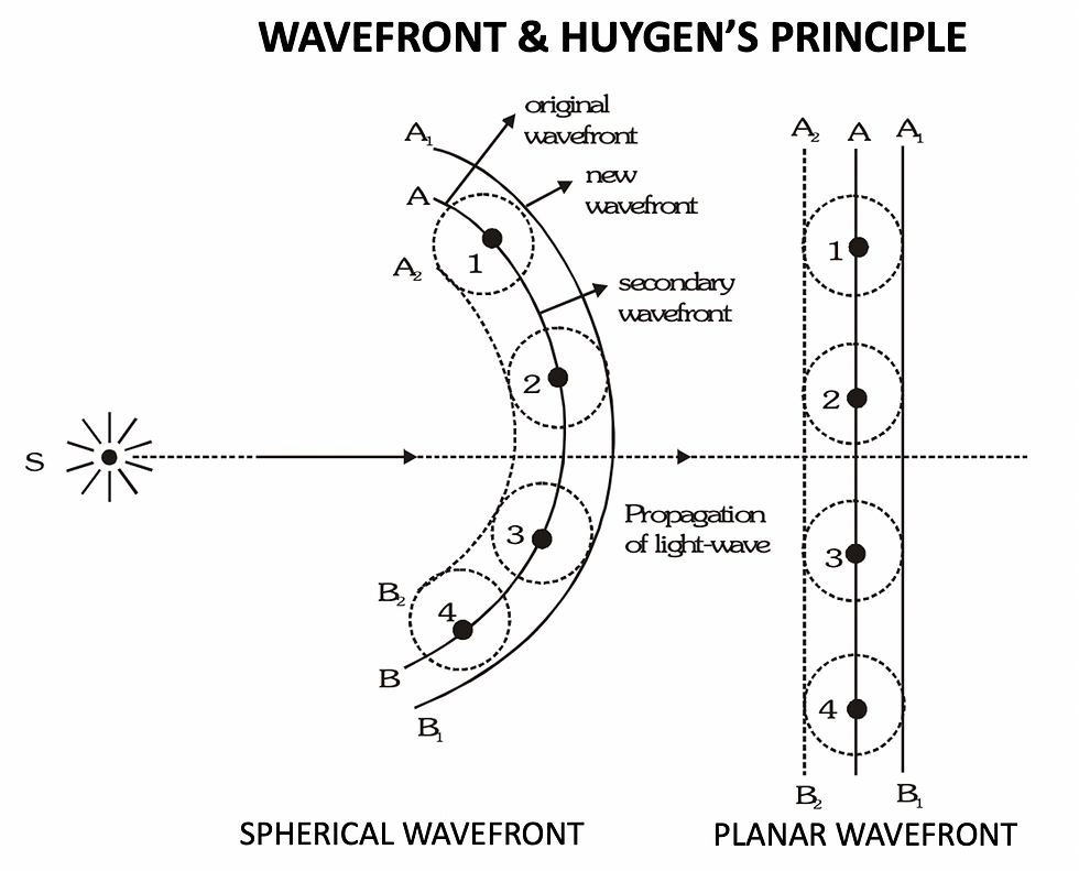
[NOTE: Huygen's principle is simply a geometrical construction to find the position of the wavefront at some later time.]
REFRACTION AND REFLECTION OF PLANE WAVES USING HUYGENS PRINCIPLE
When light enters a different medium, its speed changes. Let v1 be the velocity of light in medium 1with refractive index 'n', then
v1 = c/n
where, c = velocity of light in vacuum.

NOTE: When a wave gets refracted into a denser medium (v1 > v2 ) the wavelength and the speed of propagation decrease but the frequency ν (= v/λ) remains the same.
Remember the formula:
λ1/λ2 = V1/V2
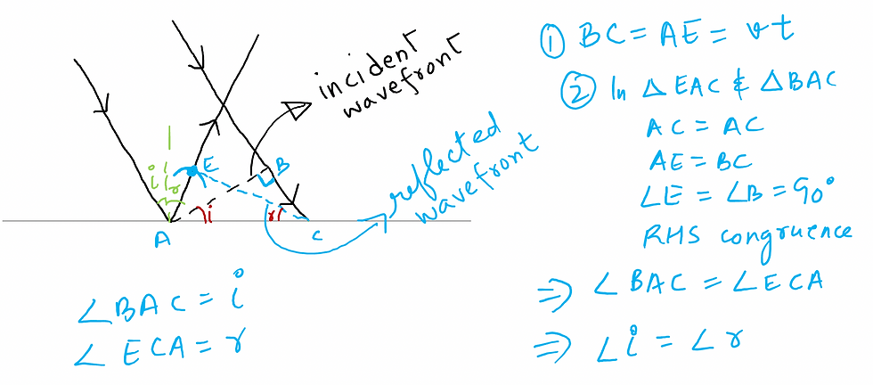
PROOF OF LAW OF REFLECTION
INTERFERENCE
In order to understand wave optics certain concepts wave need to be kept in mind. We will discuss them here briefly.
For a detailed description of these concepts, read the BLOG ON WAVES.
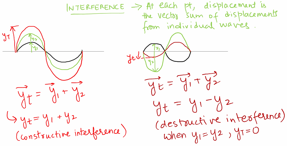
Interference is based on the superposition principle according to which at a particular point in the medium, the resultant displacement produced by a number of waves is the vector sum of the displacements produced by each of the waves.
In between the extremes of constructive and destructive interference, we need to look at the wave function.
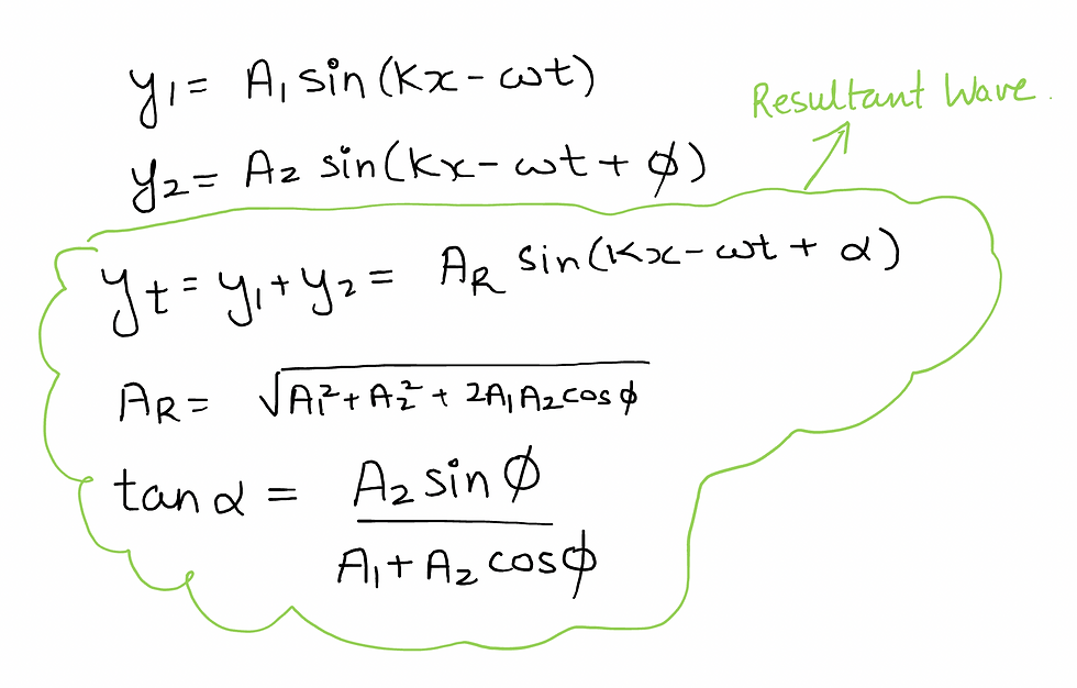
Let wave 1 be defined by: y1 = Asin(kx-wt)
Let wave 2 be defined by: y2 = Asin(kx-wt + ϕ)
[where ϕ is an angle called phase difference]
These are Coherent Waves - same frequency, same wavelength and constant phase difference. We will study wave optics concepts for coherent waves only.
The resultant wave after adding the displacements vectorially is given by:
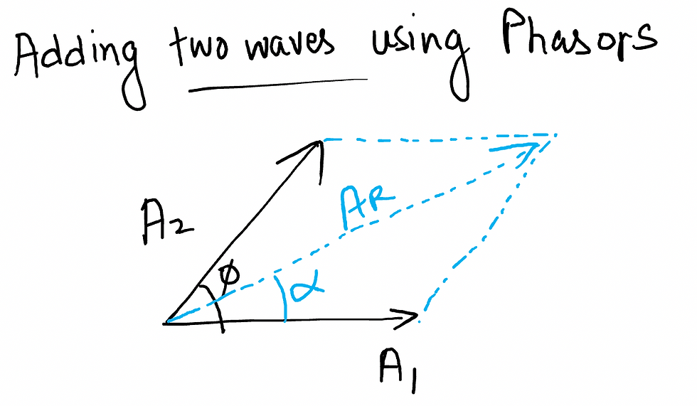
SHORT NOTE ON PHASORS TO ADD TWO WAVES
Phasors is short cut method to add trigonometric functions in Waves, SHM and Alternating Current, Alternating Voltages quickly.
[Keep in mind, phasor technique uses vector addition but it does not mean that waves, SHM, AC etc. are vectors]. In the case of waves, assume that the wave is represented by vectors where magnitude of the vector is the Amplitude of the wave and the phase difference represents the angle between the vectors. The resultant wave is the vector sum of the two waves.
SOME WAVE CONCEPTS FOR WAVE OPTICS
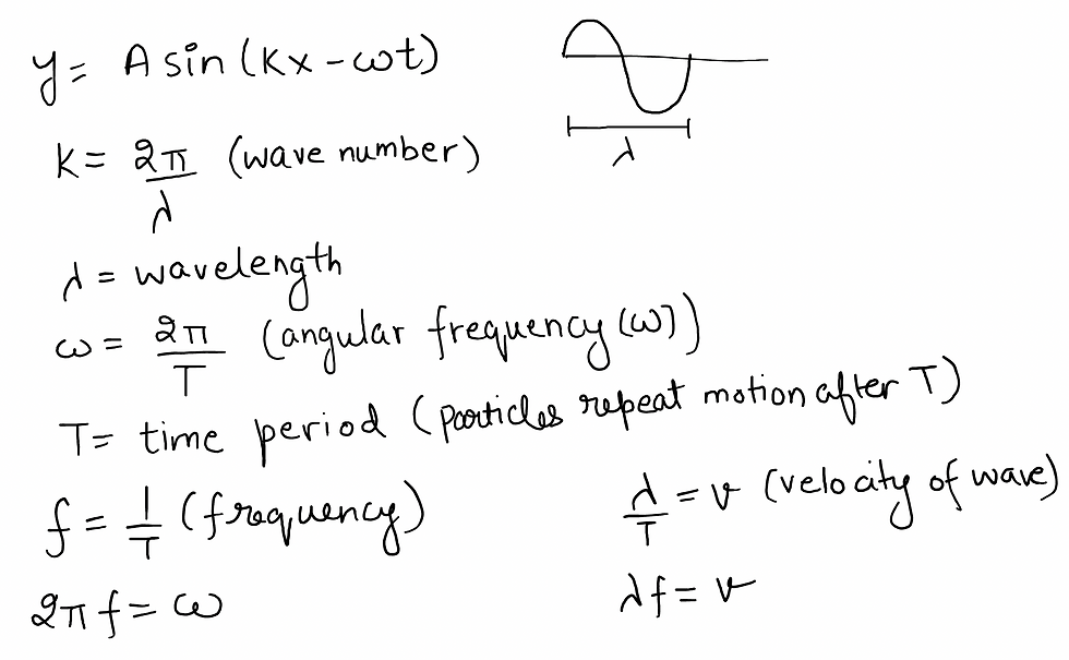
For a detailed discussion, read this blog.
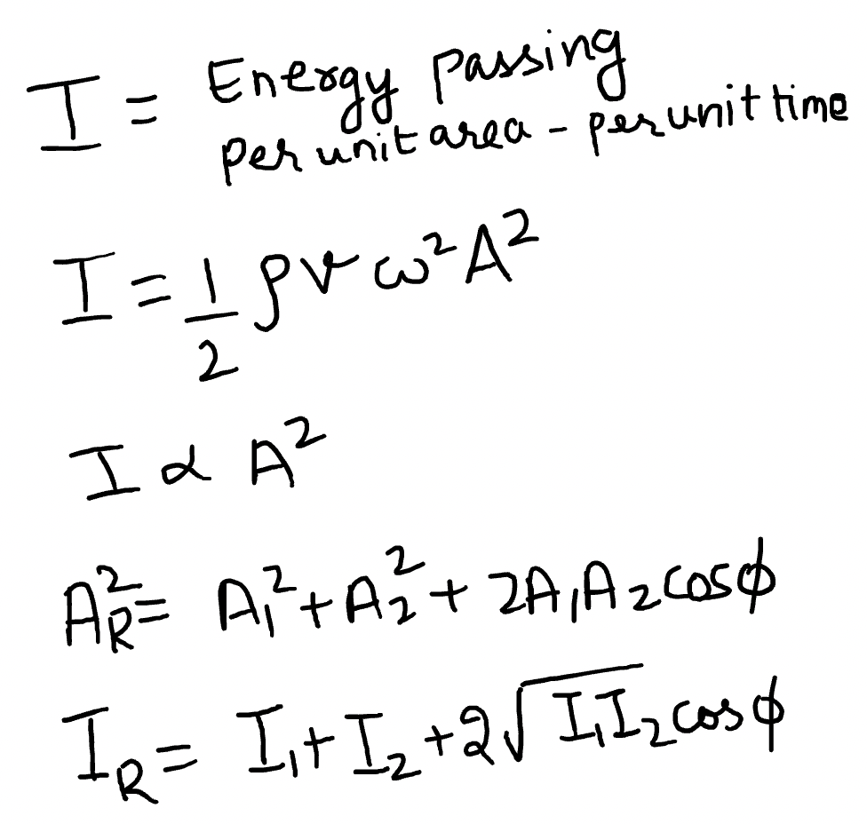
INTENSITY OF A WAVE
Intensity of a wave is defined as energy passing through a unit area per unit time. Intensity of a wave is proportional to the square of amplitude. For a resultant wave, intensity is given as follows:
INTERFERENCE: IMPORTANT CASES
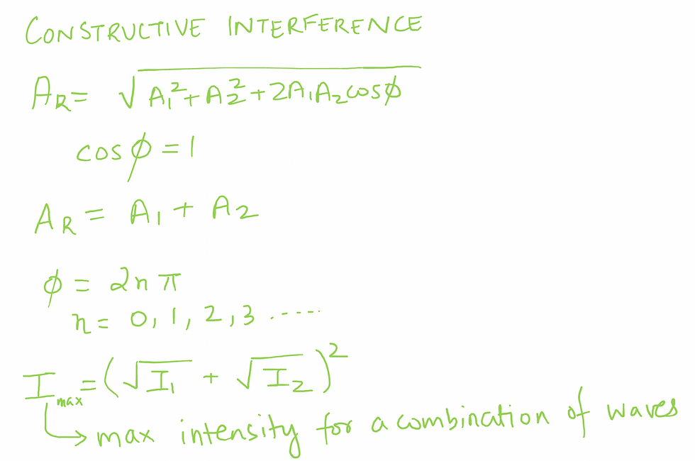
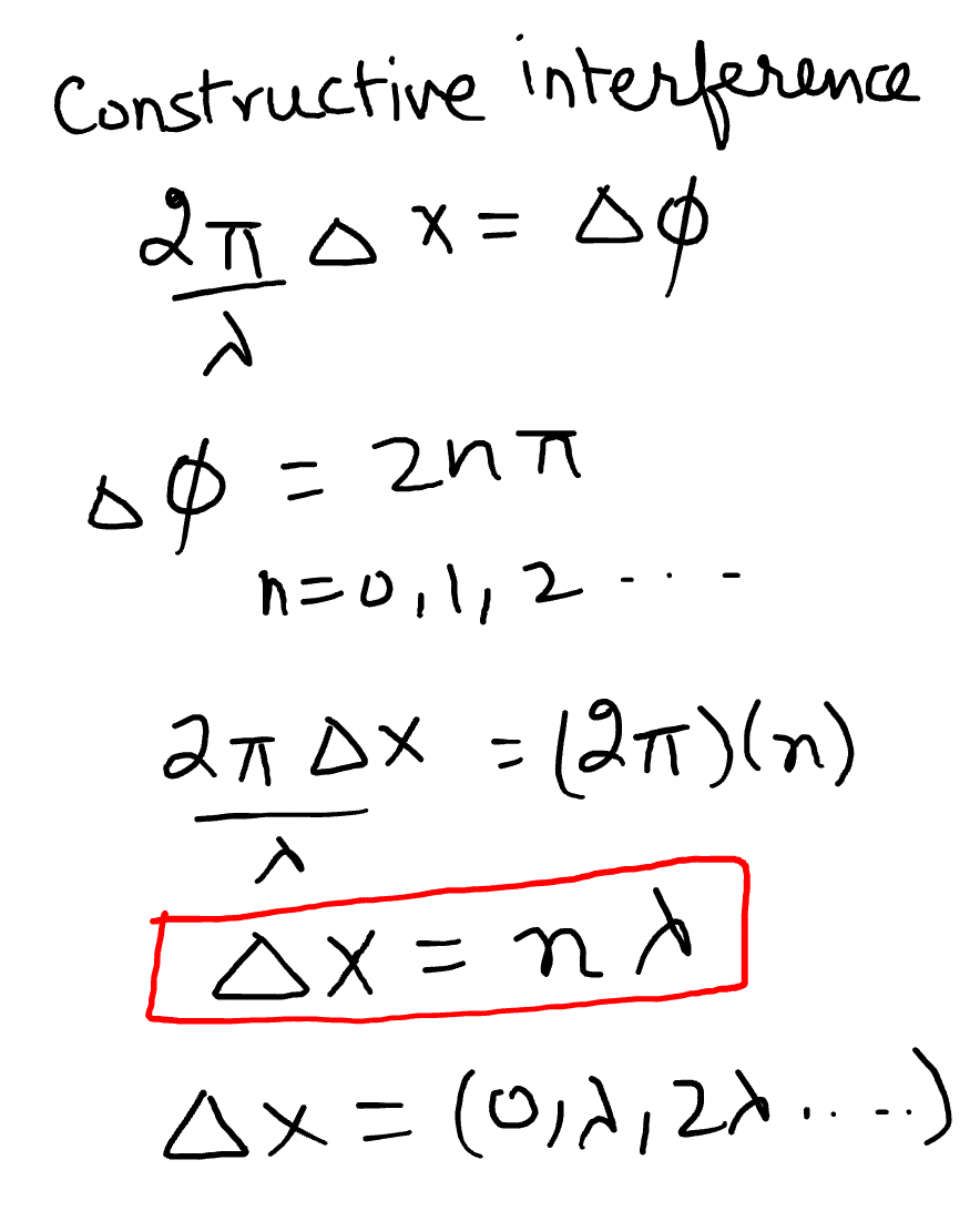
CONSTRUCTIVE INTERFERENCE
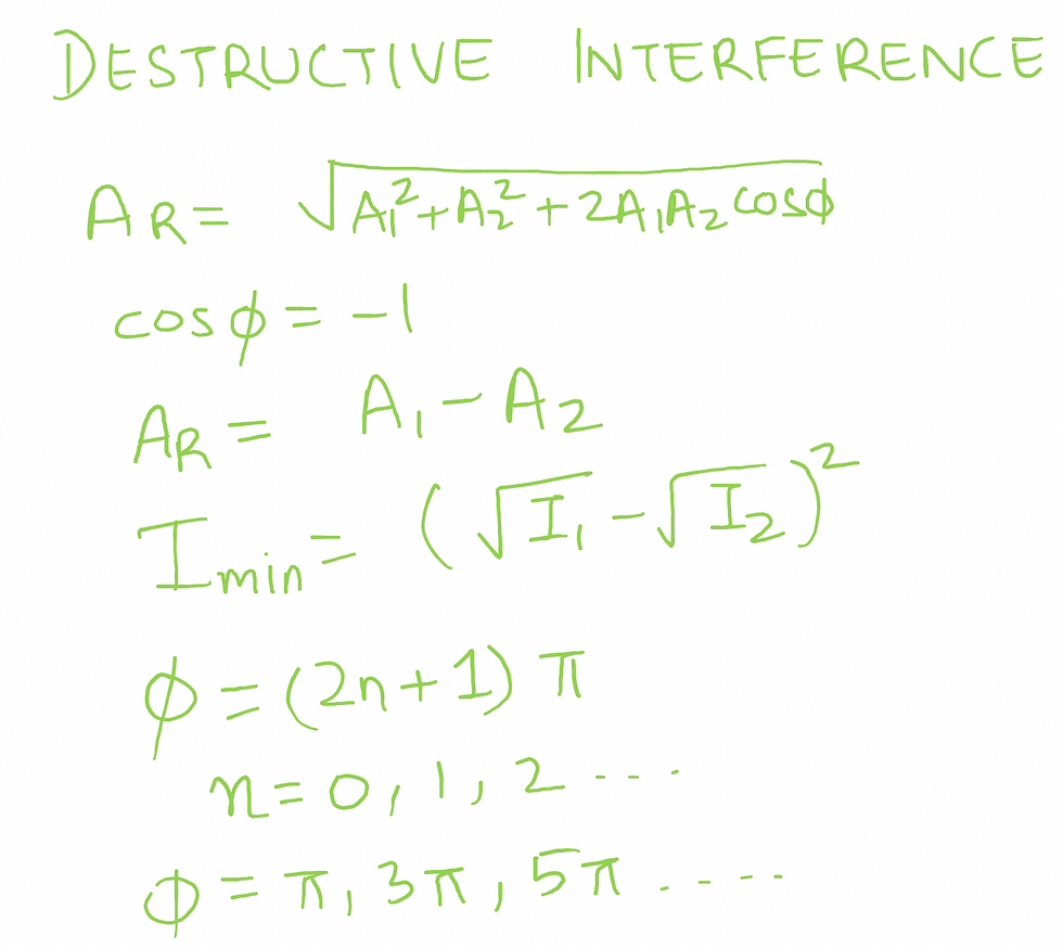
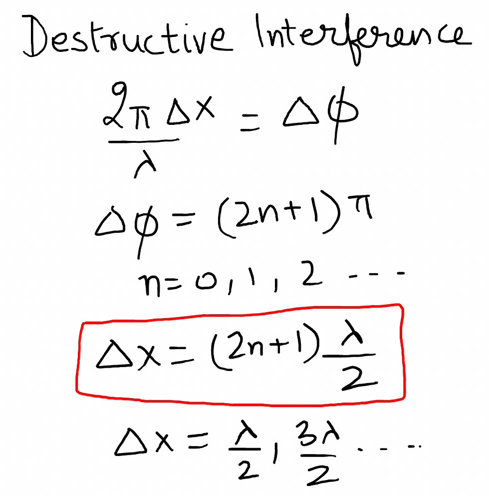
DESTRUCTIVE INTERFERENCE
WHEN COMBINING WAVES HAVE SAME AMPLITUDE
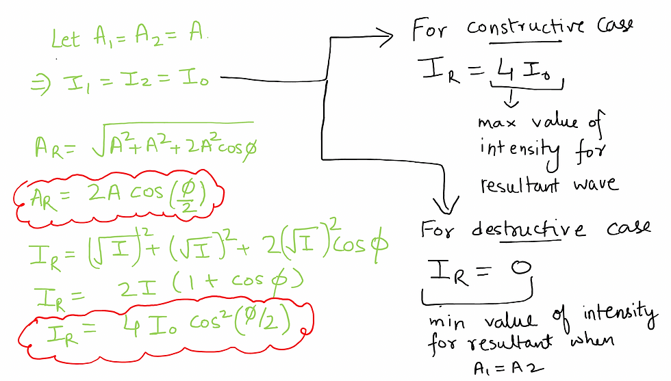
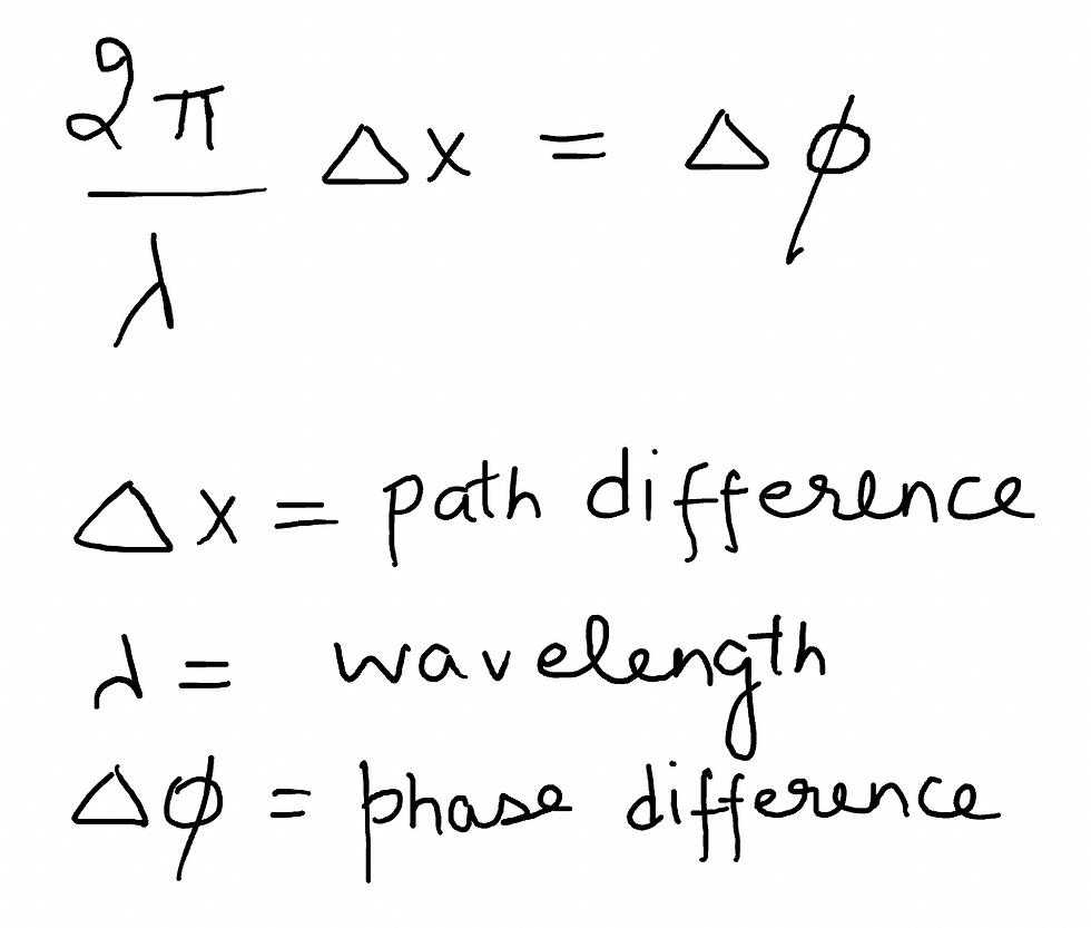
VERY IMPORTANT FORMULA FOR WAVES AND WAVE OPTICS
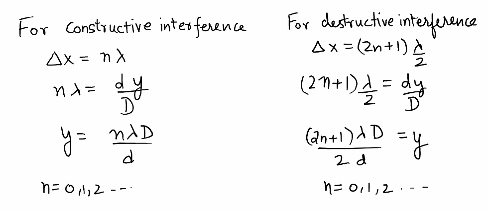
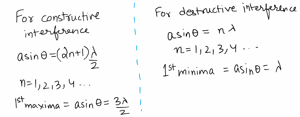
For constructive interference, path difference is given by:
For destructive interference, path difference is given by:
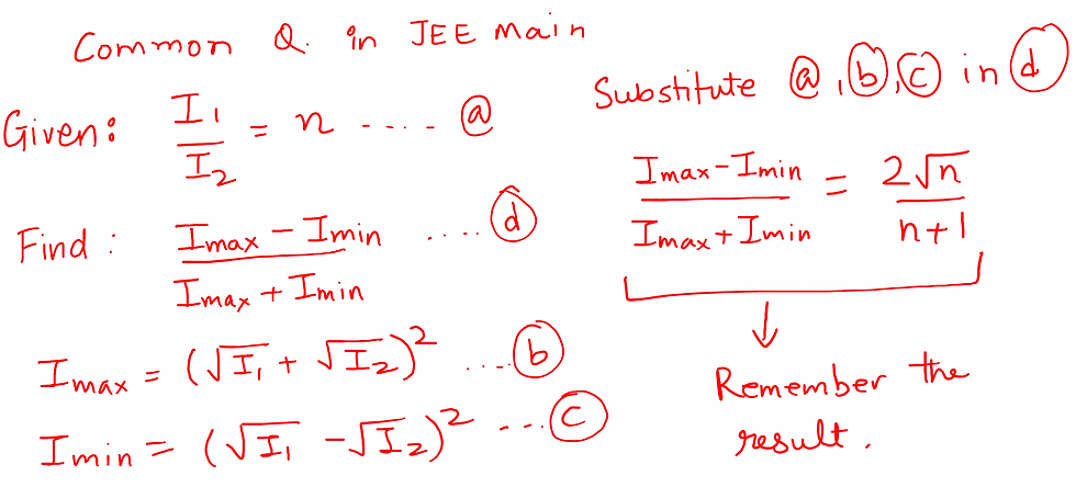
A Common Question in JEE MAIN
YOUNG'S DOUBLE SLIT EXPERIMENT
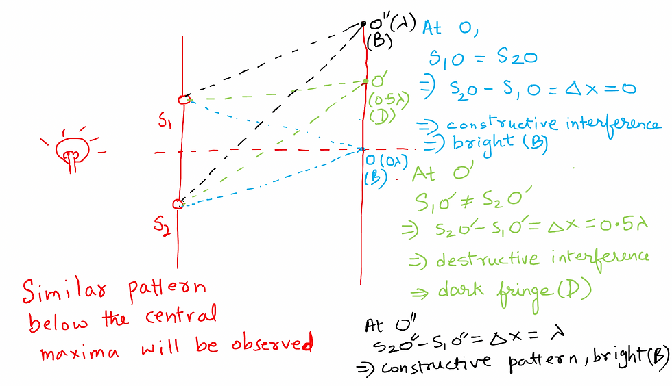
Young made two pinholes S1 and S2 (very close to each other) on an opaque screen. These were illuminated by a bright source. Light waves spread out from S and fall on both S1 and S2.
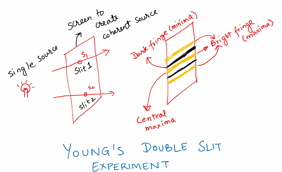
The light that emanates from S1 & S2 produces interference patterns (alternate bright and dark patterns) on the receiving screen due to a path difference.
Derivation of the Position of bright an Dark Fringes
Here we take two assumptions:
d<<D (distance between slits is much smaller than distance between slits and receiving scree)
y << D (we are observing the pattern close the the central maxima)
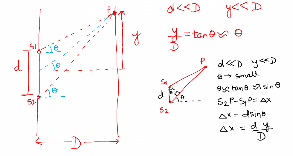
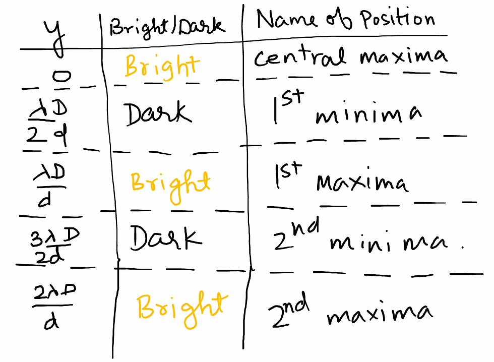
POSITION OF BRIGHT AND DARK FRINGES IN YDSE
OTHER IMPORTANT FORMULAE IN YDSE
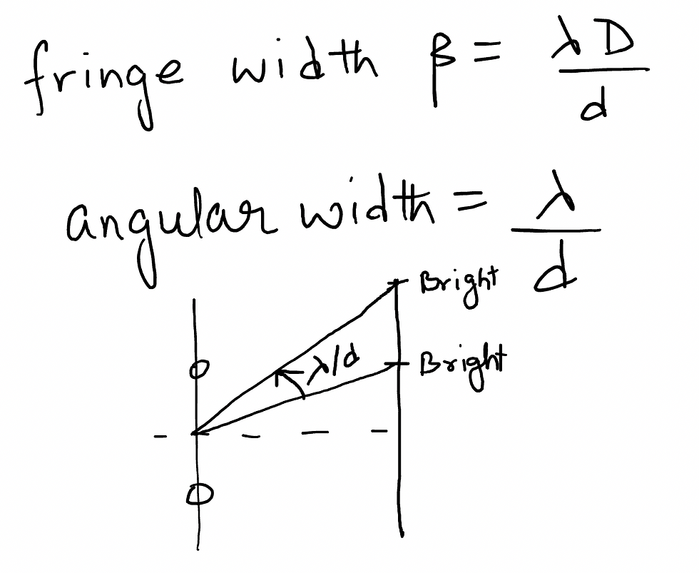
Fringe width: Distance between two successive bright fringes
Angular fringe width: Angular distance between two successive fringes. It is not dependent on 'D'.
VARIATION IN YOUNG'S DOUBLE SLIT EXPERIMENT
VARIATION 1: Immersion in a liquid
Wavelength (λ) of light changes in the liquid according to refractive indx of liquid 'n'.
λliquid = λair/n
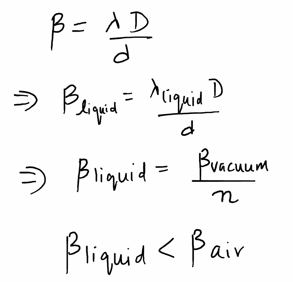
When YDSE is immersed in a liquid -
Fringe width decreases
Central maxima is formed at the same place
Pattern shrinks
Number of maxima and minima increases
VARIATION 2: Slab in Front of a Slit

Entire pattern shifts up by shift = (u-1)tD/d
Fringe width remains same
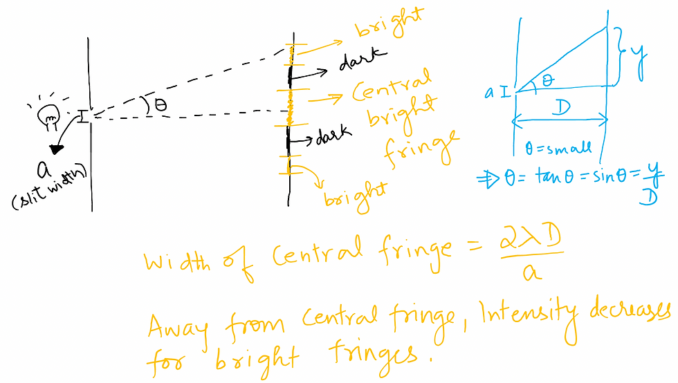
DIFFRACTION
The phenomenon of bending of waves when they travel around the obstacles of size comparable to their wavelength, is called diffraction.
Diffraction is shown by all waves. It is observable when size of the obstacle is comparable to the wavelength.
DIFFERENCE BETWEEN YDSE & DIFFRACTION
(i)The YDSE interference pattern has a number of equally spaced bright and dark bands. The diffraction pattern has a central bright maximum which is twice as wide as the other maxima. The intensity falls as we go to successive maxima away from the centre, on either side.
(ii) We calculate the YDSE interference pattern by superposing two waves originating from the two narrow slits. The diffraction pattern is a superposition of a continuous family of waves originating from each point on a single slit.
POLARIZATION
This phenomenon is valid only for transverse waves.
Light waves are transverse in nature; i.e., the electric field associated with a propagating light wave is always at right angles to the direction of propagation of the wave.
A polaroid consists of long chain molecules aligned in a particular direction.
The electric vectors (associated with the propagating light wave) along the direction of the aligned molecules get absorbed.
Thus, if an unpolarised light wave is incident on such a polaroid then the light wave will get linearly polarised with the electric vector oscillating along a direction perpendicular to the aligned molecules; this direction is known as the pass-axis of the polaroid
Given below is the description of Malus' Law which gives us the intensity of light after passing through two polaroids.

POLARISATION BY SCATTERING
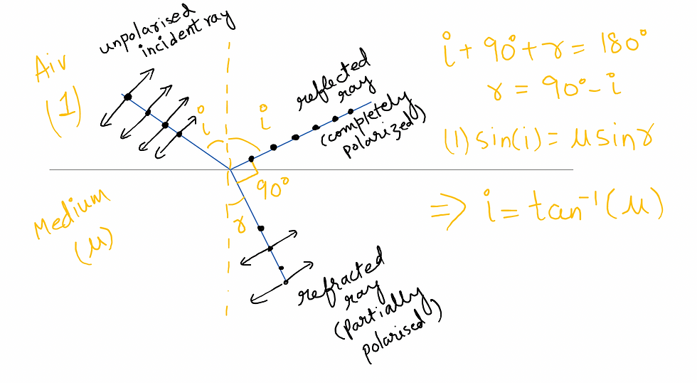
BREWSTER's ANGLE
When unpolarised light is incident on the boundary between two transparent media, the reflected light is polarised with its electric vector perpendicular to the plane of incidence when the refracted and reflected rays make a right angle with each other.
Thus, when reflected wave is perpendicular to the refracted wave, the reflected wave is a totally polarised wave.
The angle of incidence in this case is called Brewster’s angle
Hope you can REVISE WAVE OPTICS FOR JEE MAIN PHYSICS from this guide to answer all varieties of JEE MAIN PYQs.
Thanks a lot!
If you want to get in touch for guidance related to JEE, career etc. I am always available at the at www.savai.co.in or WhatsApp me @ 7982286138
Please share www.savai.co.in in case you find our content helpful.]
Comments